
There is an extant video, from a traffic camera, I believe, that shows the moment of the onset of the the FIU bridge collapse of March 15, 2018.
I found a video showing the video on a screen with some people watching, and it is in a loop, which makes it easier to examine. It shows not only the moment, but the location of the onset, consistently with reports that the collapse “began at one end.”
Here is a two-frame gif from the video, showing the moments just before and after the onset:
I think this view is quite revealing, as it shows that the collapse was initiated by a break in the roof, meaning that it was bearing a critical load, or in crude terms, “It was the only thing holding up the bridge.”
This all makes sense from a simple point of view, considering the departure of the installation procedure from the initial design.
Here is a photograph of the bridge just before the installation, when it was being maneuvered into place. It is a very clear view, and answers many questions I had about the initial design … i.e. Had it been altered or even abandoned?
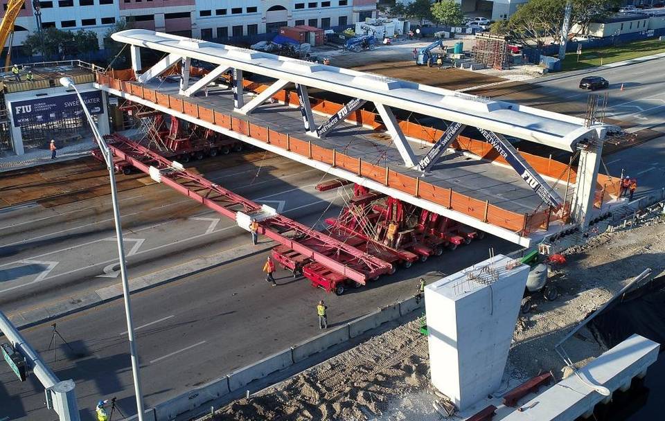
A comparison with an available diagram of the “cable-stay” design shows that all the design elements on the span itself are in place, and the installation allows for the addition of the tower, and a second shorter span, as shown in the design:
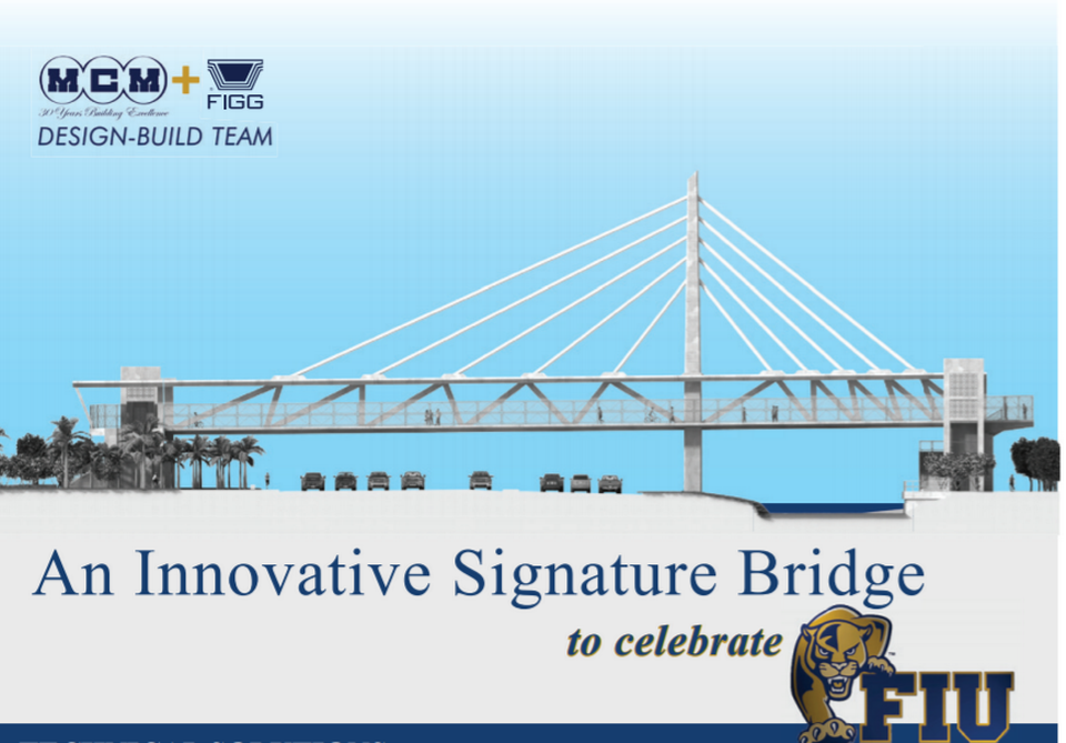
A careful comparison of these shows that the configuration of the struts between the deck and the roof matches up very well, within the limits allowed by the images, of course.
Also, note the very prominent attachment points along the center of the roof. These “points” of attachment are very large and complex in appearance. I read that these attachment elements are not cables, per se, but “pipes”, but as per the design, they would have functioned as cables, that is, provided support under tension.
Compression vs. Tension
Here is a simple schematic analysis of an idealized truss, showing that in this configuration, the top and end pieces are under compression, and the bottom deck is under tension:
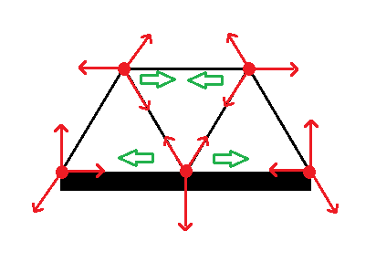
The red arrows show the forces on the nodes ( red dots ) due to the struts and deck, as per the requirement that the sum of the forces at each node must be zero.
So, the strut along the top is pushing outwards, and by reaction, it must be under compression. Conversely for the deck.
This logic applies exactly to the FIU bridge, and to me it accounts very well for the chain of events.
Well, I don’t mean to get into a particular analysis. I’ll just say that in my mind, “The Emperor has no clothes.”