I came up with this in an Aha Moment, actually while lying in bed, as I was contemplating whether two 3×3 squares of a sudoku could be identical. The answer came quickly to me when I thought that if these squares were diagonally juxtaposed, they would be compatible if their elements were translated diagonally by one, along the same diagonal, of course, and these new ( identical ) squares were added to form a 2X2 sudoku.
Then, in a flash, I saw that this operation would allow THREE identical squares along a diagonal, with the diagonal translation performed twice, and with a third time producing the original square. That was it.
So the scheme is :
A B C
C A B
B C A
where A, B, and C are the 3×3 grids :
1 2 3 9 7 8 6 5 4
4 5 6 2 3 1 8 9 7
7 8 9 5 6 4 3 1 2
and the solution grid is:
1 2 3 9 7 8 6 5 4
4 5 6 2 3 1 8 9 7
7 8 9 5 6 4 3 1 2
6 5 4 1 2 3 9 7 8
8 9 7 4 5 6 2 3 1
3 1 2 7 8 9 5 6 4
9 7 8 6 5 4 1 2 3
2 3 1 8 9 7 4 5 6
5 6 4 3 1 2 7 8 9
So that’s the long and short of it, but it remains to specify the automorphism. Indeed, this whole question was perplexing to me, as I hadn’t been thinking in those terms.
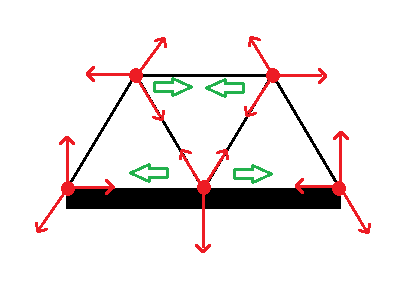
Well, in the first place, we may specify the cyclic permutations of the “stacks” and “layers” ( i.e the columns and rows of the 3×3 squares ) .
Each of these, in our case, may be replicated, or reversed, by a permutation of the digits.
But also due to our particular configuration, these permutations may be replicated by permutations among the columns and rows within the stacks and layers.
So, at this point, I can only wonder how this particular case fits into the enumeration specified in the Wikipedia article.
So, it’s a mind bender, of this I feel sure.
We may also note that, as specified above, the downward rotation by one, among the layers, followed by, or “times”, the leftward rotation by one, among the stacks, “equals unity”, i.e. does not change the layout.
This is a consequence of the triplication of the three unique squares, and not usually to be found among other automorphisms.
… all presented for your consideration!


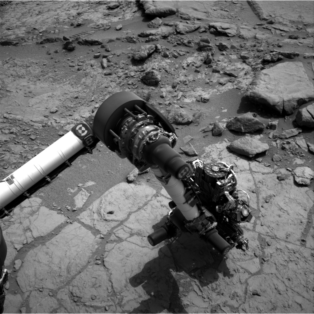
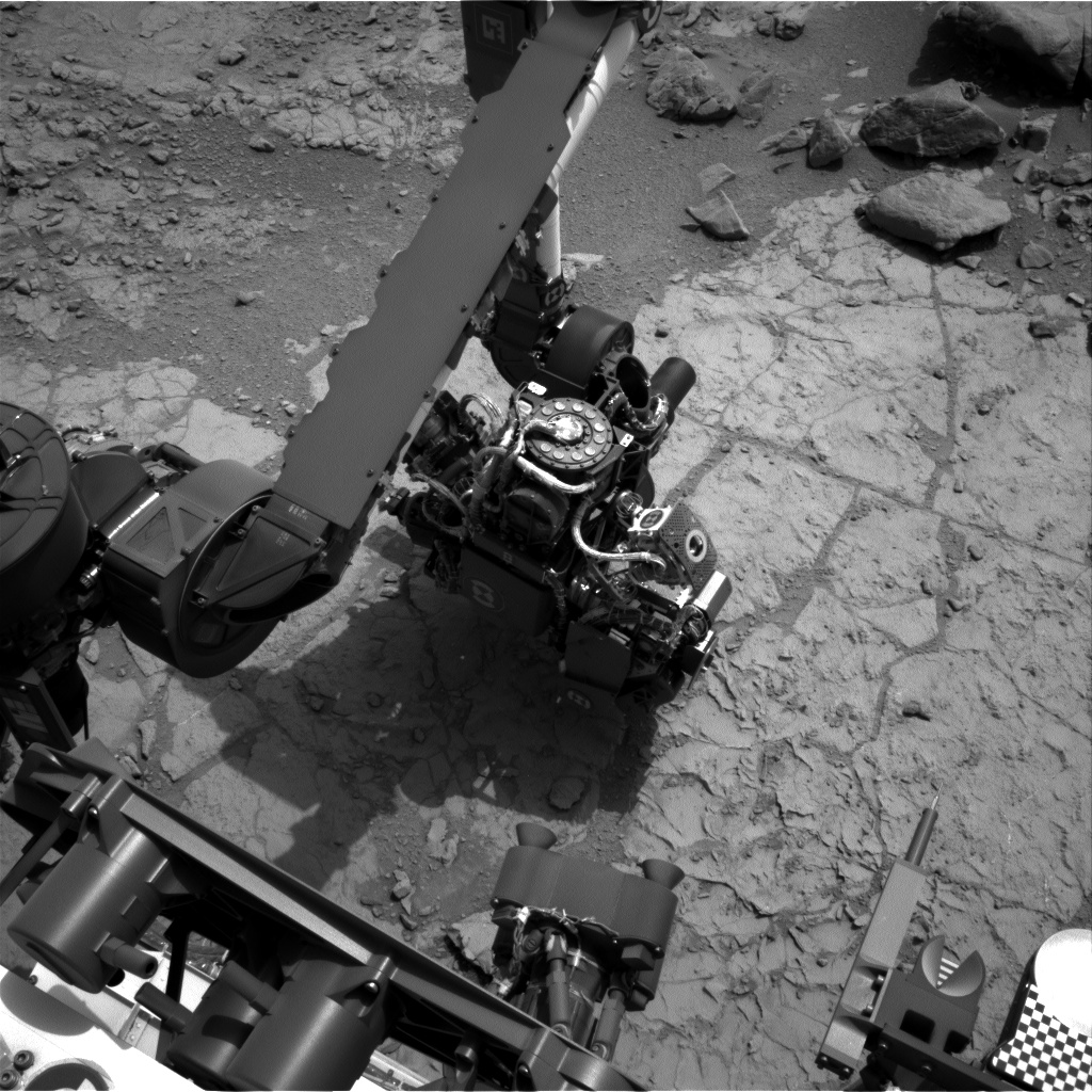 After endless wanderings around the area of the announced drill site, it appears that they’re finally doing the deed, according to this sol 170 Navcam image, which shows the drill in position. That “telephone dial” is the opposite end of the drill axis, so the business end is at the surface. This is the first image I’ve seen showing this deployment.