About Lew

Lifetime science geek. 'Nuf said.

Lunar Eclipse of 1/20/2019

It was very cold on lunar eclipse night here in the Chicago area, but also very clear, so this counts as good luck.

I set up my Orion Starmax 127 on its equatorial mount right in the driveway, but with no clocking – just the knobs. I used my Nikon D5100 camera body mounted for prime focus photography. The moon is just slightly too large for this ( especially the “supermoon” ! ) but I wanted a large image.

I adjusted the exposure time and ISO sensitivity as it approached totality, so that the sequence I’m showing here was at the “Hi 1” ISO setting with a shutter speed of 1/25 of a second.

Here is the first image of the sequence

The bright rim was just a very faint glimmer to the naked eye, and I’m not sure why it seemed to persist for so long.

The images are 2464 x 1632 pixels and are reduced to 493 x 397 in MS Paint.  I further edited them in MS Paint to position them consistently for the animation. I made the image size 540 x 420 and filled in the boundary ( after positioning ) using the “dropper” ( i.e. Color Picker ) to match the dark sky. This worked pretty well.

There was one frame where I clipped the bright rim, and this created a jarring discontinuity. So, I ( rather crudely ) filled it in with a facsimile. It’s easy to see as it goes by, but I think it makes the viewing easier.

The animation runs from 10:48 PM to 11:00 PM ( CST, ) according to the camera timestamps.

Animated gif of onset of totality

An interesting automorphic sudoku

I came up with this in an Aha Moment, actually while lying in bed, as I was contemplating whether two 3×3 squares of a sudoku could be identical. The answer came quickly to me when I thought that if these squares were diagonally juxtaposed, they would be compatible if their elements were translated diagonally by one, along the same diagonal, of course, and these new ( identical ) squares were added to form a 2X2 sudoku.

Then, in a flash, I saw that this operation would allow THREE identical squares along a diagonal, with the diagonal translation performed twice, and with a third time producing the original square. That was it.

So the scheme is :

A B C
C A B
B C A

where A, B, and C are the 3×3 grids :

1 2 3   9 7 8   6 5 4
4 5 6   2 3 1   8 9 7
7 8 9   5 6 4   3 1 2

and the solution grid is:

1 2 3   9 7 8   6 5 4
4 5 6   2 3 1   8 9 7
7 8 9   5 6 4   3 1 2

6 5 4   1 2 3   9 7 8
8 9 7   4 5 6   2 3 1
3 1 2   7 8 9   5 6 4

9 7 8   6 5 4   1 2 3
2 3 1   8 9 7   4 5 6
5 6 4   3 1 2   7 8 9

So that’s the long and short of it, but it remains to specify the automorphism. Indeed, this whole question was perplexing to me, as I hadn’t been thinking in those terms.

Well, in the first place, we may specify the cyclic permutations of the “stacks” and “layers” ( i.e the columns and rows of the 3×3 squares ) .

Each of these, in our case, may be replicated, or reversed, by a permutation of the digits.

But also due to our particular configuration, these permutations may be replicated by permutations among the columns and rows within the stacks and layers.

So, at this point, I can only wonder how this particular case fits into the enumeration specified in the Wikipedia article.

So, it’s a mind bender, of this I feel sure.

We may also note that, as specified above, the downward rotation by one, among the layers, followed by, or “times”, the leftward rotation by one, among the stacks, “equals unity”, i.e. does not change the layout.

This is a consequence of the triplication of the three unique squares, and not usually to be found among other automorphisms.


… all presented for your consideration!

Hands-On Spherical Trigonometry

Spherical Trigonometry is used as a gateway to abstract mathematics because it can be taught as the study of the  geometry of  an intrinsically curved surface, without reference to its embedding in a “flat” 3-d space, as we experience it. So this is the preferred and usual method of teaching.

Still, I found myself a bit unsatisfied when I recently looked up, for study, the Spherical Law of Sines, which stands in direct analogy to the Law of Sines of plane trigonometry, with one important variation. That is, the sides, a and b, as referenced in the latter, become sin a and sin b in the former … very mysterious!

I found that the proofs tended to be algebraic in nature, depending on various “trigonometric identities” and I wondered if I couldn’t come up with something a little more “concrete” using constructive methods of traditional spatial ( Euclidian ) geometry.

So, doodling around, I found that I had great difficulty visualising 3-d constructions by reliance on 2-d diagrams, i.e. drawn on paper.

So I decided, well, I’ll make a model out of wood.

Of course, that requires a little doing. The obvious method is to cut out a sector of a sphere along central planes, but that isn’t exactly easy, and it wastes most of the sphere ( even if you can make several this way from one sphere. )

Also, wooden craft or carving balls are expensive, and usually rather small. So I decided to cut one from a block. I could buy a bag of 8 or 10 suitable blocks for a few dollars, and I could use two of the flat sides for the plane surfaces of the defining central planes. This would give me a nice RIGHT spherical triangle, while minimizing the carving effort.

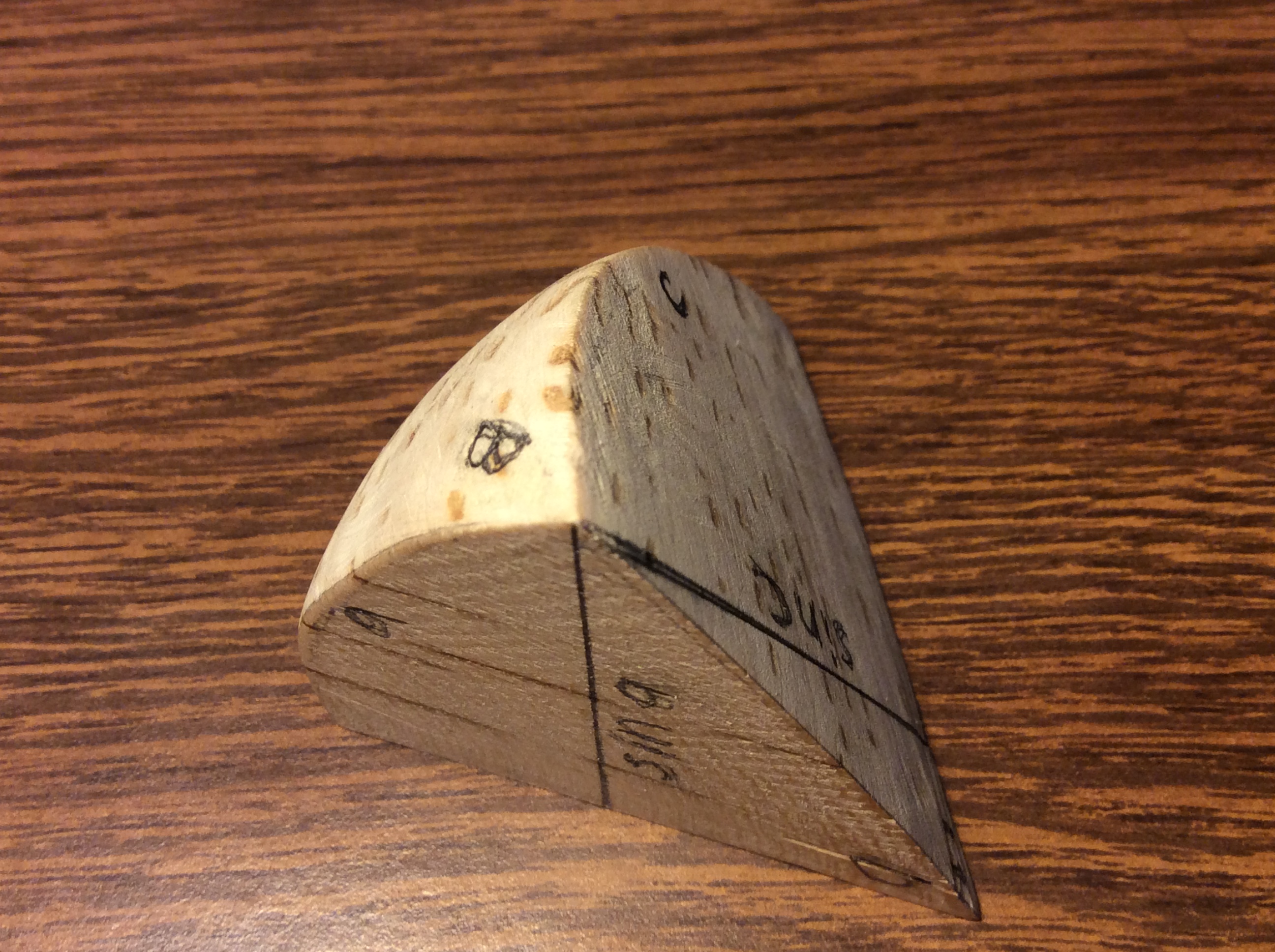
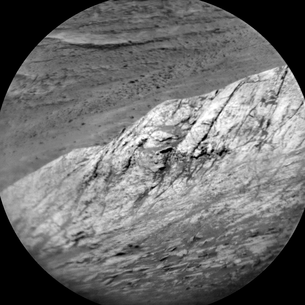
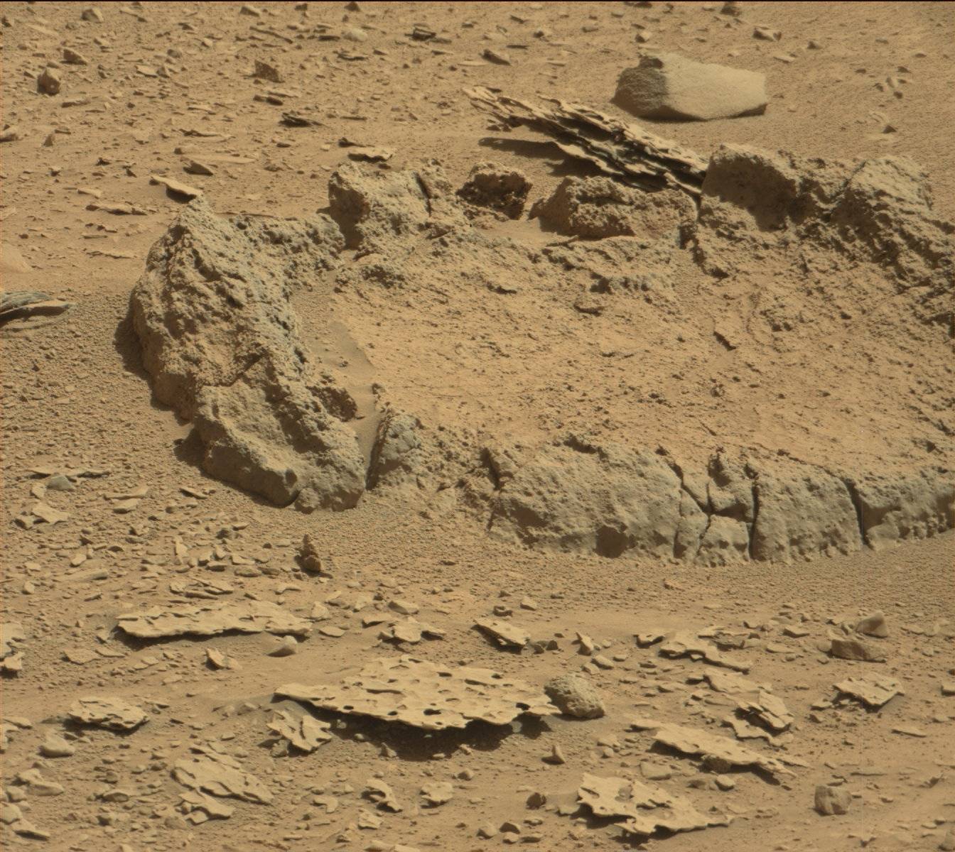
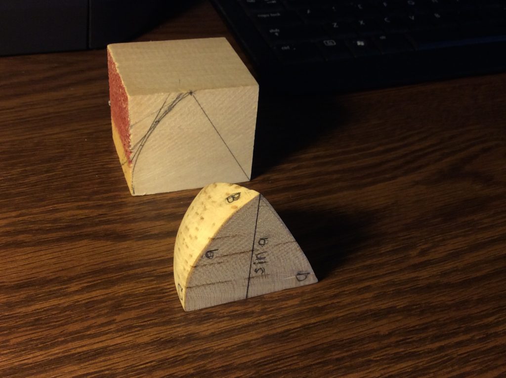
So, here is the completed result, along with another block showing the preliminary mark-up:

BTW, forming the curved surface wasn’t as laborious as I thought it would be. I could get reasonably close by cutting easily defined tangent planes to the surface, and then sandpaper made short work. Of course, it’s not perfect!

Napier’s Rules and the Spherical Law of Sines

Well, I had already noticed that the Spherical Law of Sines could be reduced to one of Napier’s Rules, in this case (R2) as named in the Wikipedia article on Spherical Trigonometry.

(R2)      sin a    =   sin A   sin c

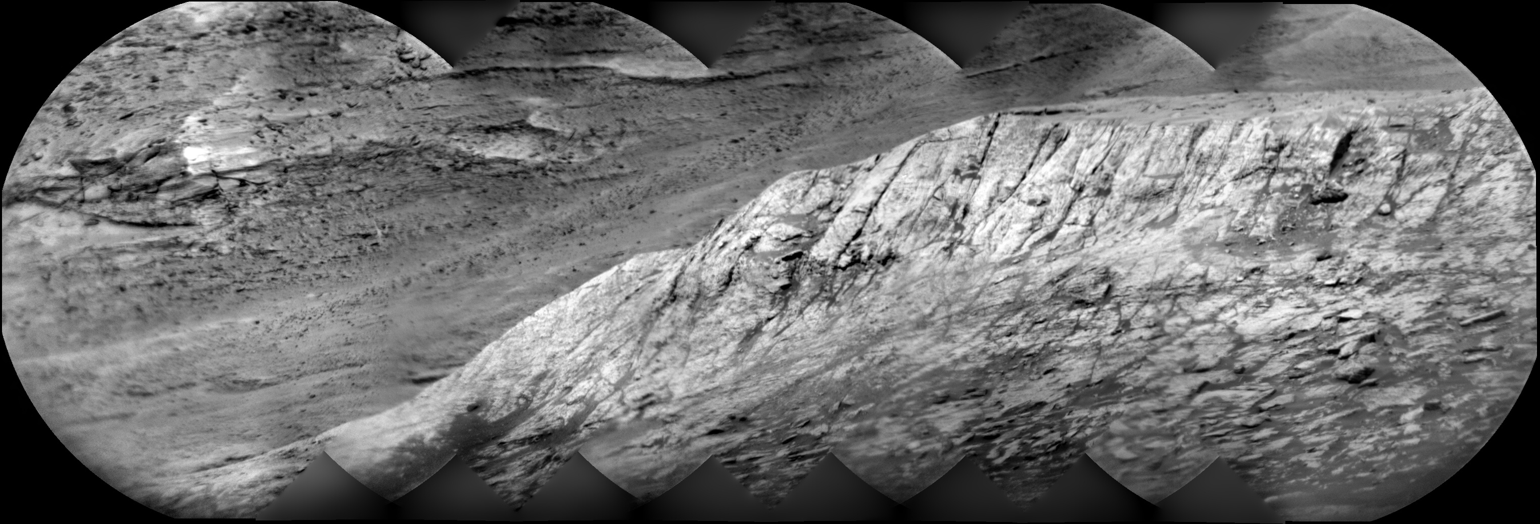
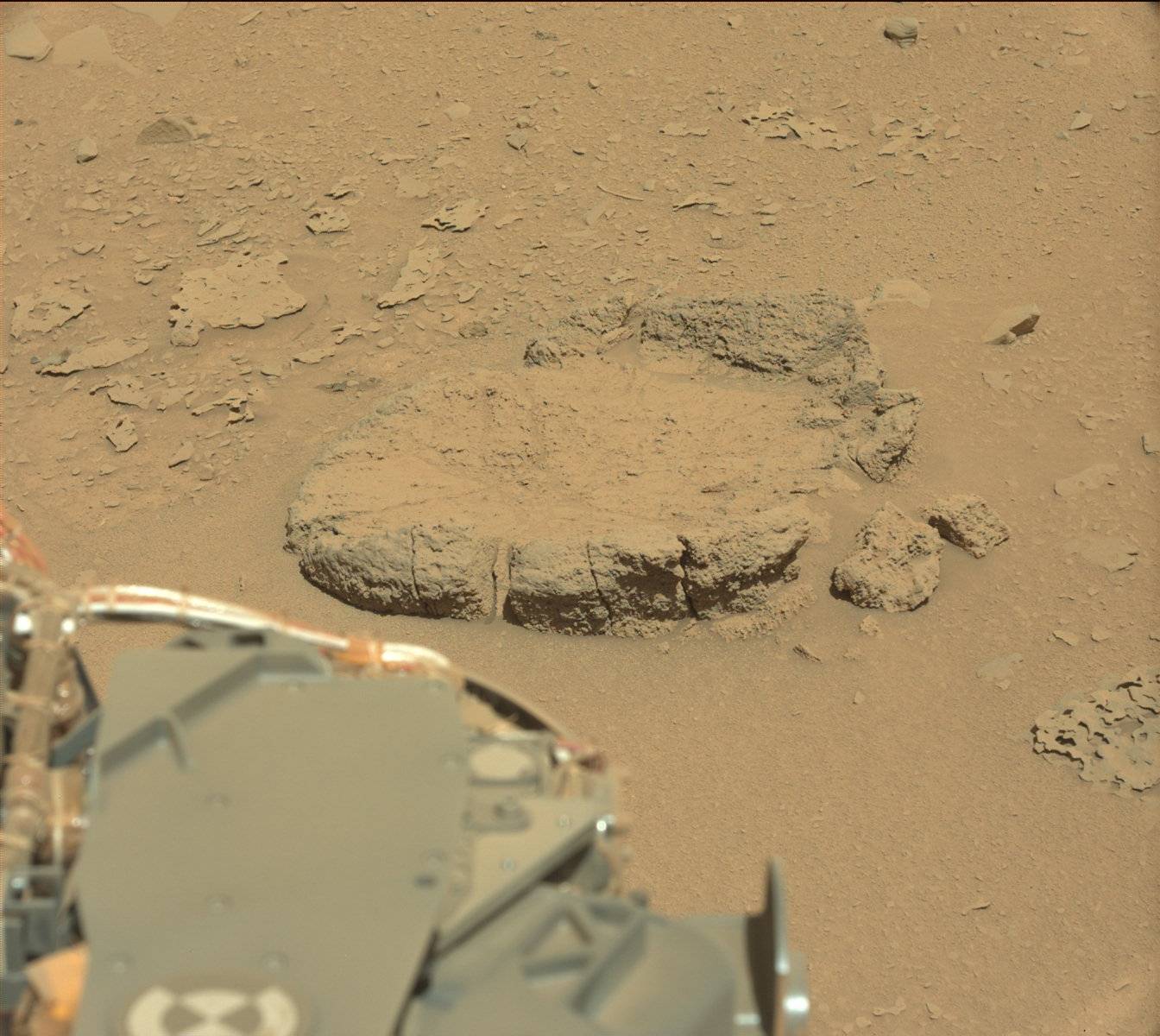
In the image below, angle A is at the base of the spherical triangle at the top of the photo, and measures the dihedral angle at bottom right. So it’s a simple application of “opposite over hypotenuse” to see that   sin A = sin a / sin c , which is (R2) above.

Note also that sin a and sin c are defined by the central angles, a and c, which measure the sides, a and c,  of the spherical triangle.

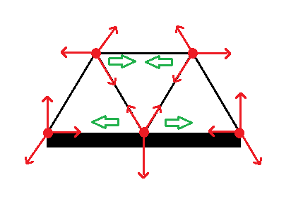
To get the Spherical Law of Sines all that is required is to place next to it another right spherical triangle sharing side a, along with the perpendicular plane face subtending it, to form a “general” triangle.

The shared altitude, sin a, then plays the same role in the proof as the shared altitude used in the proof of the Plane Law of Sines.

… and that’s all I have to say about that.

The Hot-wire Foam cutter and the Spherical jig

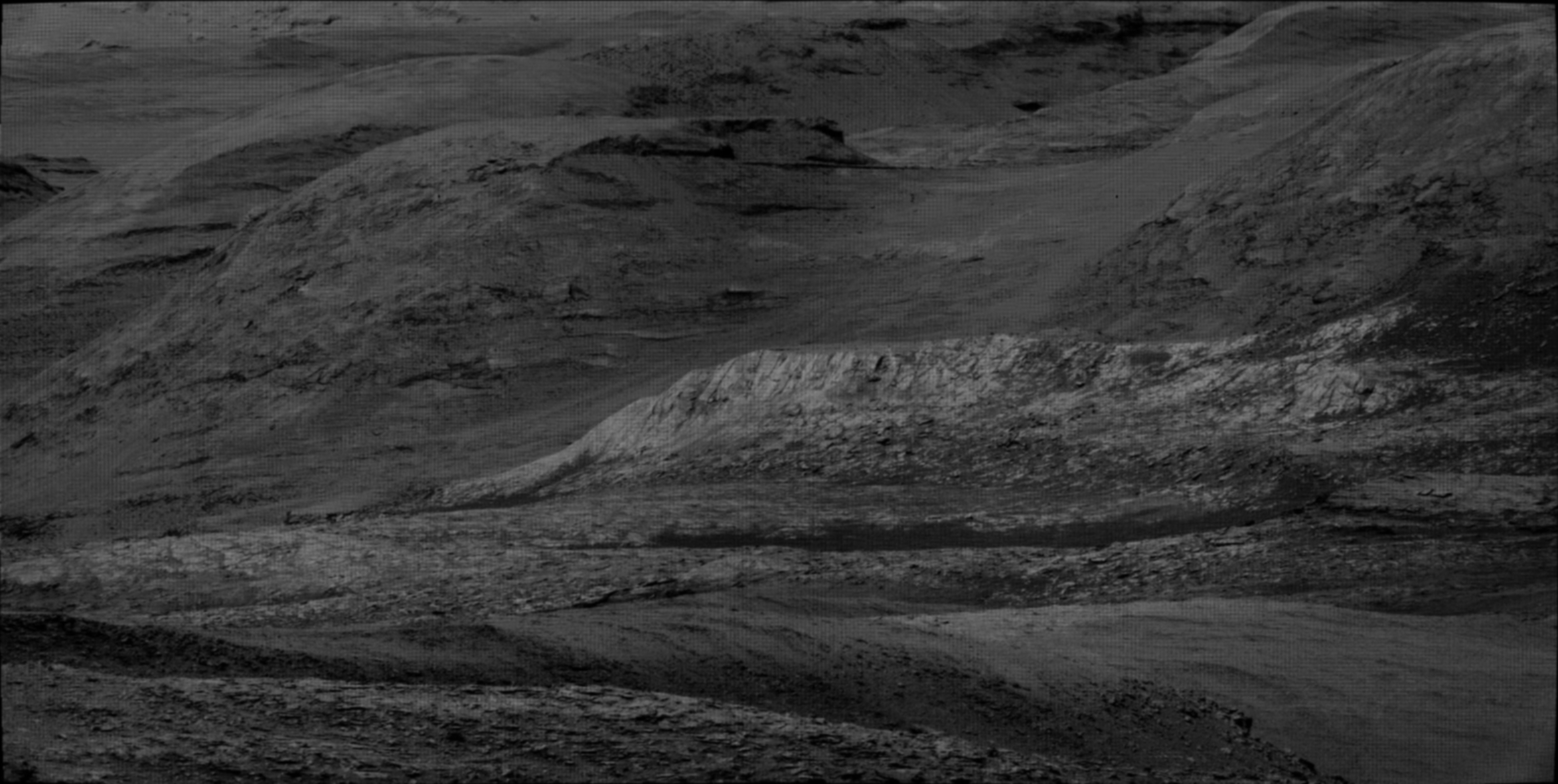
Now for the really fun part:

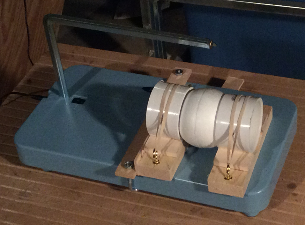
This is a hot-wire foam cutter equipped with a “spherical jig” of my own devising. As you can see it holds a 3″ foam sphere to be cut in half ( as adjusted . )  By cutting the same sphere in half  “three  ways”, I can form a spherical triangle along with its subtending solid central angle, just like the carved wooden model above.

Of course, I automatically get 8 such triangles. In the general case these will be 4 distinct triangles, along with their mirror inverses.

A Spherical Zoo

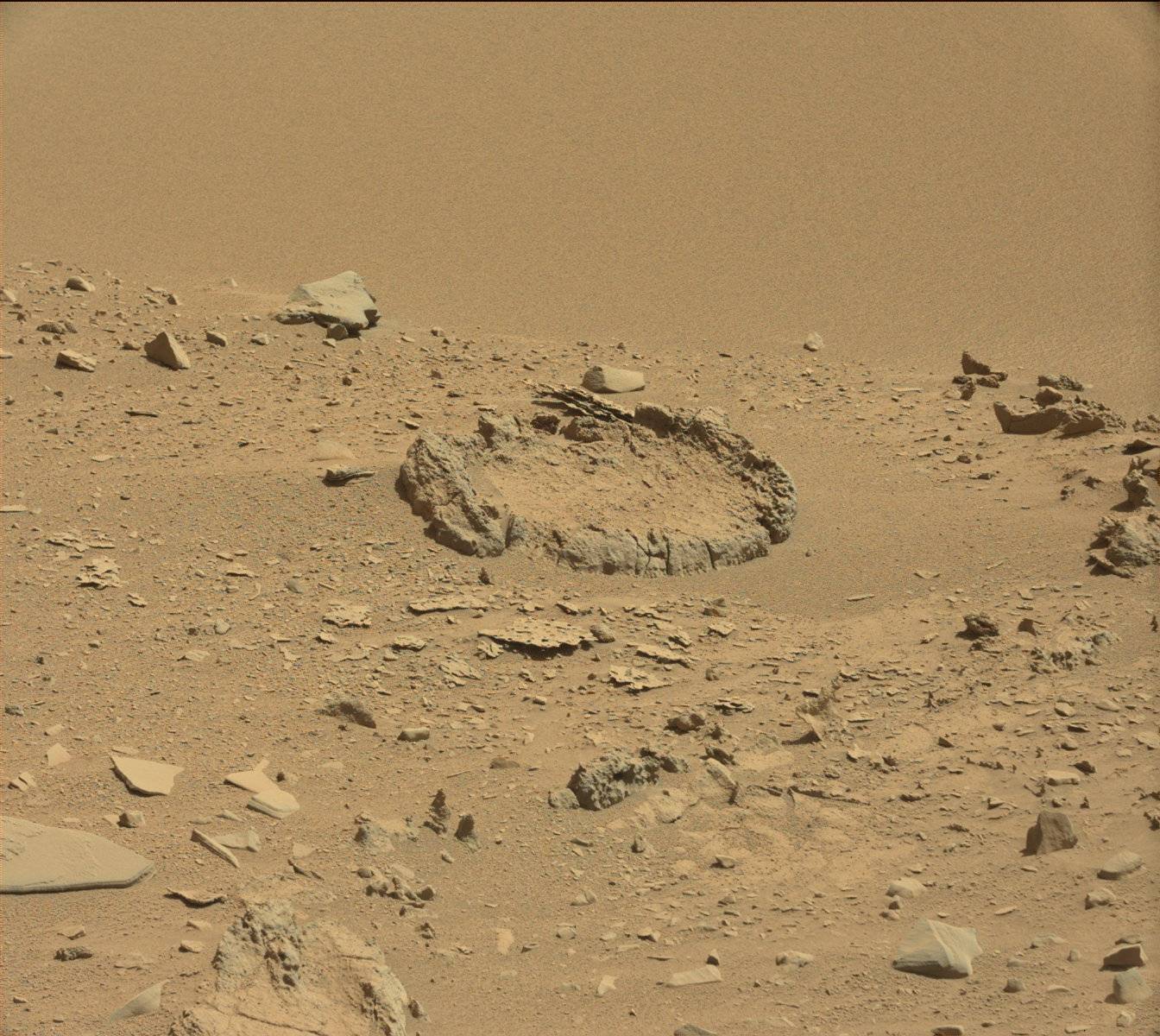
Here’s a “special” case of a such a production, contrived to produce a “large” equilateral triangle ( of course two of them ) and whatever else “falls out” :

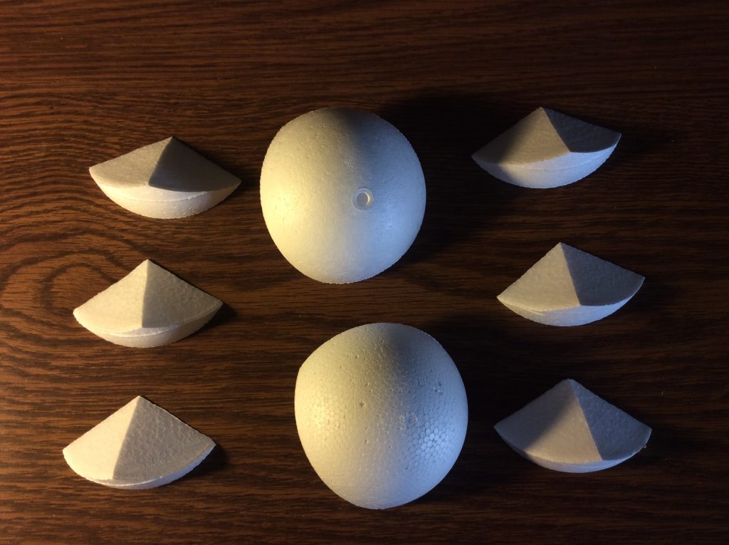
The “large” equilateral triangles, inverses of each other, but in this case identical, are in the center.

Then six identical isosceles triangles are arranged on the sides. These form an equatorial ring between the two polar equilateral caps.

I first thought that this accounted for all possible isoceles triangles, but these are just a subset. They are the isoceles triangles which have the length of each ( equal )  side as the supplement of the base. That is, the base plus one side equals a 180 degree arc.

Just part of the arrangement that I think of as the Spherical Zoo.

Some “Nuts and Bolts”

I had been pondering how to organize this Zoo, and I was thinking in terms of the edges of the triangles of a partitioned sphere. This seems natural, since a “small” triangle can have arbitrarily short edges, just like plane triangles.

However, the triangles of a partition can also be specified by their ( corner ) angles, and this has the advantage that we can use the “spherical excess” rule, which gives the area of a spherical triangle in terms of the “excess” above 180 degrees, or “pi”. In fact, the area, in units of R squared, regarded as “Unity” for a given sphere, is exactly this value, expressed in radians.

So, using this scheme, I came up with a simple “map” of all the possible divisions of the sphere into triangles, in terms of A, B, and C, the angles of any one of the 8 triangles in such a division.

Well, with regard to units, we can have our cake and eat it too by specifying these angles in terms of pi/180 radians, which corresponds to “degrees”, but reminds us that the area is measured in “steradians”, of which there are 4 pi to be accounted for among the 8 triangles of a division, using the spherical excess rule. Note that this is nothing to do with “square degrees” … which we won’t touch.

In fact, since our “degree” is pi/180 radians, the 4 pi steradians  of the sphere are measured by 720 degrees, or 720 X pi/180. I explain all this so that we can do examples with angles, and areas, expressed in small integers. That this is possible is remarkable in itself!

… so then my “map” :

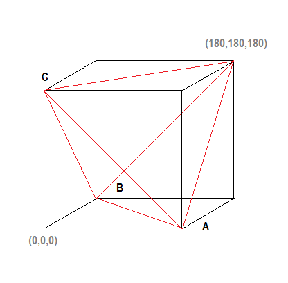
… The angles A, B, and C , with values 0 thru 180, as indicated, will specify a valid spherical triangle whenever they are the coordinates of a point lying inside the tetrahedron drawn in red.

Very simple!

… to be continued


The Point of Collapse

There is an extant video, from a traffic camera, I believe, that shows the moment of the onset of the the FIU bridge collapse of March 15, 2018.

I found a video showing the video on a screen with some people watching, and it is in a loop, which makes it easier to examine. It shows not only the moment, but the location of the onset, consistently with reports that the collapse “began at one end.”

Here is a two-frame gif from the video, showing the moments just before and after the onset:

I think this view is quite revealing, as it shows that the collapse was initiated by a break in the roof, meaning that it was bearing a critical load, or in crude terms, “It was the only thing holding up the bridge.”

This all makes sense from a simple point of view, considering the departure of the installation procedure from the initial design.

Here is a photograph of the bridge just before the installation, when it was being maneuvered into place. It is a very clear view, and answers many questions I had about the initial design … i.e. Had it been altered or even abandoned?

A comparison with an available diagram of the “cable-stay” design shows that all the design elements on the span itself are in place, and the installation allows for  the addition of the tower, and a second shorter span, as shown in the design:

A careful comparison of these shows that the configuration of the struts between the deck and the roof matches up very well, within the limits allowed by the images, of course.

Also, note the very prominent attachment points along the center of the roof. These “points” of attachment are very large and complex in appearance. I read that these attachment elements are not cables, per se, but “pipes”, but as per the design, they would have functioned as cables, that is, provided support under tension.

Compression vs. Tension

Here is a simple schematic analysis of an idealized truss, showing that in this configuration, the top and end pieces are under compression, and the bottom deck is under tension:

The red arrows show the forces on the nodes ( red dots ) due to the struts and deck, as per the requirement that the sum of the forces at each node must be zero.

So, the strut along the top is pushing outwards, and by reaction, it must be under compression. Conversely for the deck.

This logic applies exactly to the FIU bridge, and to me it accounts very well for the chain of events.

Well, I don’t mean to get into a particular analysis. I’ll just say that in my mind, “The Emperor has no clothes.”


In search of “Bloodstone Hill”

The Mars Curiosity Mission Update for Sols 1954-1956 includes the stated goal of … an RMI mosaic of “Bloodstone Hill.”

RMI stands for “remote micro-imager” and refers to the use of the ChemCam camera for simple image acquisition, without sectroscopy. It has a long focal length, so it makes a fair “spot zoom”.

Then the Mission Update for Sols 1955-1957 is titled,

Sol 1957-1958: Onward towards gray patch

and features this image: … so I thought for a long time that this was “gray patch”. I don’t want to put anything on the Curiosity Team. The principal goal is not to explain everything to ME. If I have to work a little bit for it, so be it.

The text does say,  inter alia, “… We’ll also take a Mastcam mosaic of “Bloodstone Hill,” another target from the weekend plan that warranted further investigation – this area is featured in the black and white RMI image above. ” OK.

I made the RMI mosaic from sol 1955 ( including the above image, ) and here it is:


I thought the circular framing would interfere with the mosaic, but the long focal length and narrow FOV kept the stitching very nice.

So where is it? What are we looking at? For the promised Mast Cam mosaic, I only found two images in the very annoying rastered grey rendition. Here they are side by side with a “tetch” of Gaussian blur, and some contrast enhancement:

OK! Great context! … except I still couldn’t place this in a broader scene. Note there is no skyline! This makes it difficult.

Well, I made another mosaic from the Right Navcam 

Do you see it? I think it’s very hard to spot.  Look at the top center of the rightmost pane, and the elongated whitish feature is the feature at the center of the Mast Cam mosaic above. If you click the image and enlarge it, you will be convinced.


Mars rock circle in tabloids

A Mars Curiosity image of a “rock circle” has appeared in the British tabloids in the last few days,  touted by “alien hunters” to be an artifact of some kind .

The NY Post gave secondary coverage and carefully stated that it was “recently found” among the images by said “hunters.”

From the setting, I could see that it did not match the recent terrain being covered ( we’re up to sol 1734, ) and I did spend a little time looking back over the route to find a likely spot. I was pretty lucky, although I will credit my intuition, as I found it as a Mastcam image from sol 528

In fact, this image was evidently not a chance acquisition, since they immediately acquired this followup image, also on sol 528

Here we get a more detailed view, and it looks somewhat more “natural”, I think, with noticeable irregularities. Then, on sol 529, they actually “moved in for a look” and acquired this image

Here you can start to get an idea of its formation. It seems to be sort of a disk with the center scoured low, like a lozenge. Of course, this is just one small feature! From what I understand, the landscape as we see it is formed almost exclusively by very slow erosion from the dust storms.

BTW, the images were acquired on 2014-01-30 13:53:37 UTC,  2014-01-30 13:54:26 UTC, and  2014-01-31 15:46:03 UTC, over three years ago.

Also, here is the section of the path showing the location

The “dog-doo”

This is the name which occurred to me when I saw this feature, and true to my habit, I’m sticking with it. Here it is in a sol 1700 Mastcam shot, which I already included in a panorama linked in “Ozymandias”, below.

It does seem to be a distinctive feature. The darker blobby looking rock on the top doesn’t seem to fit with the more predominant thinly layered rock, which are easily seen as eroded remnants of dust-formed strata.

Well, at this point ( sol 1700 ) I had high hopes that Curiosity would make a bee-line for it and do a major examination, but these met with frustration.

Coincidentally, I read at about this time, an ONION article on the “Morbid Curiosity Rover”. Of course this is a pun, and nothing to do with “morbid curiosity”, but a facetious evaluation of  Curiosity’s “morbid” temperament, as note that the official MSL accounts allow for Curiosity to speak in the first person. The Onion found that Curiosity was uncooperative, and even unresponsive, and given to obsessive lingering and drilling activities.

I thought this to be a wry comment on the incompatibility of the inscrutable science campaign with the preferences of those of us more concerned with sight-seeing.

So these thoughts came to the fore as Curiosity roved closer and closer to the “dog-doo”, but seemed to deliberately eschew imagery of it. I thought, and still think, that it was partly because it was up-slope from Curiosity, and the imagery had a tendency to pan on a level plane, so that we were treated to extensive views of “where it had been” but the looming features ahead, including the “dog-doo”, were chopped off at the ankles. ( If you don’t believe me, check it out! )

Well, there were a few Navcam shots, but this feature was obviously not a target, and at closest approach, Curiosity veered to the east, and focused on other things, this to my ultimate frustration, I thought.

But then, there was a late adder to the sol 1726 SUBFRAME products from the Mastcam. These are monochromatic, and have a funky grid superimposed, but OTOH, are highly detailed, and feature a magnificent view of the “dog-doo” at the extreme right.

Accordingly, I offer this truncated version of what is approximately a 180 degree panorama, consisting of  2 of the 20 component images:

In Paint.net, I used just a “tetch” of Gaussian blur ( a minimal setting of 1 ) to alleviate the crosshatching of the “grid”, and gave it a sepia tint, which I modified with a slight reddening of the hue.

“You’re in the shop!”

Where Is Curiosity?

The MSL website helpfully provides maps to show the progress of Curiosity, but lately, circumstances have led to some frustration.

Curiosity has reached the southern limit of the displayed range, and it is heading south, so it is hard to see what is in store. In addition, the large scale inset is placed so that it obscures significant adjacent topography … as shown here …

Never fear! I have the Hiview software and image files, which I downloaded some time ago, and these include the imagery that is the basis for these maps. So here I display a  small scale ( … N.B. a small scale displays a large area … )  image with the approximate boundary of the sol 1707 inset map marked.

You’ll note that the “foothills” of Mt. Sharp are well distant to the south. The features there were evident in the panoramic views from the landing site, as see my  Sol3 panorama  post from Dec 5,2012. ( This was my first Mars Curiosity post. )

Curiosity is more than halfway there from the landing site, but I’m not sure what the schedule is, or the planned path.

“Hills peep o’er hills, and alps on alps arise!”


Ozymandias

The latest vistas from Curiosity put me in mind of Shelley’s sonnet.

“Look on these works, ye mighty, and despair.”

Of course, these are not the ruins of some civilization, but purely inanimate landscape. Yet, everything takes a form through a very leisurely evolution, compared to earth, and there it all sits, like some incredible junkyard.

Here is a simple panorama from the mastcam images of sol 1698.

… click to enlarge!

… Here’s the same scene on sol 1700, except for a forward displacement of Curiosity’s POV.

The very prominent knoll in the left foreground on sol 1700 can easily be located in the left middle ground on sol 1698.

The prominent features from the center to the lower right in the sol 1698 view are no longer in view on sol 1700.

Here’s a sol 1705 Navcam view which can be matched up with the sol 1700 Mastcam view, above.

Curiosity has advanced to a position in the sol 1700 view, just in front of the 3 large “rocks” near the center of that view. This formation appears in the sol 1705 view on the left center. It can be identified by the form of the sand, or dust, drifted against them.


The Martian Tree Stump

The “tree stump” on Mars was in the news this month, and it is indeed an interesting formation, of which there are countless examples in the Curiosity image gallery.  I don’t mind such fanciful descriptions, since it does bring attention to these images, and in fact my attention has flagged badly in the last few years, after having followed them assiduously in the early days.

I still have my PTGui panorama maker, and my “curiosity”, so I followed up on this one.

Since “You’re in the shop” I’ll share a minor glitch which vexed me greatly just yesterday, but today’s a new day and all is well.

I composed the following panorama which contains the frame from the Mast Camera that was publicized as showing a “tree stump”

Of course, it’s missing a piece! This does show that the panorama is composed of 8 separate ( overlapping ) images. But it is certainly a detraction. I spent maybe an hour trying to figure out what was wrong before I went ahead and let PTGui figure it out.

If you “click to enlarge”, then click the “+” to magnify, you will see the whole thing in the resolution of the “stump” panel that was in the news.

Well, then, today I found the following in the Raw image gallery:

So there we have it. ( This is an excerpt with the header note pasted on. ) So of course it was a simple matter to patch in and form the full panorama:

Much better! But what about this “stump” ? I looked for other images, and found the following from sol 1648, whereas this was sol 1647:

This is a panorama of 5 images from the mast cam, in color this time, as they usually are. Curiosity had moved “overnight” and you can see the large “fin” , which is to the right of the “stump” in both images, but this time the view of the “stump” shows lateral extension, indicating that the sol 1647 image was “edge on”.

Never fear, at center bottom we have a cylindrical post with some kind of runic marking! The poetry of Mars is never dead.